So I’m finally getting back to updating and using the GRBL wire bender, so I have to actually use it for something. I had built it to be able to bend various springs, when I can’t get ahold of exactly the right spring, so let’s go though a basic spring design. The other use is for bending copper wire into antenna shapes, but that’s further down the spiral…
Types of springs
Each type works a little differently in the code so let’s start with some definitions:
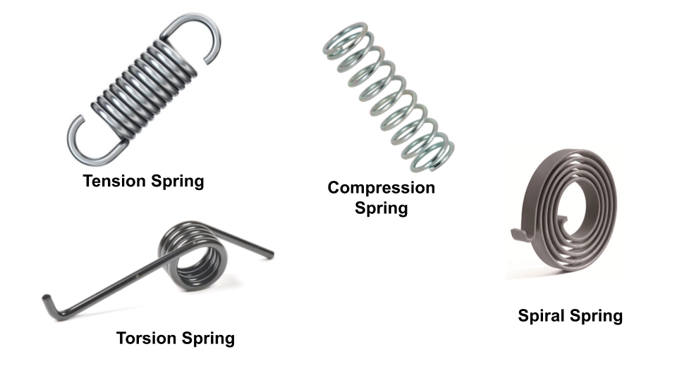
The bender really only can do springs made of wire, so disc / Belleville springs, and leaf springs don’t even enter into this conversation, so the types I’m targeting is:
- Tension Springs
- Compression Springs
- Conical Springs
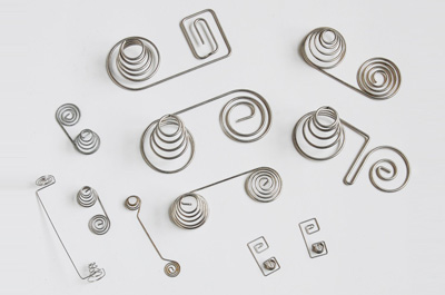
- Spiral Springs
- Torsional Springs
- Compound variations of above
Spring construction
The spring body
All of these types start with a coil of some sort, as the base and then some sort of legs, The coil could be flat, as such as a spiral spring, close together like a tension spring, spread apart like a compression spring, or a lofted spiral like a conical spring. The wire diameter, the number of coils and the spacing between the coils changes how the spring responds
The legs
The leg styles are basically three different styles, there is a straight wire, a straight wire with a hook, a loop, or a bunch of coils together. For example a tension spring typically has a loop or a hook, whereas a compression spring typically has coils together as the end, and a torsion spring, or a spiral has two straight wires.
Spring rates
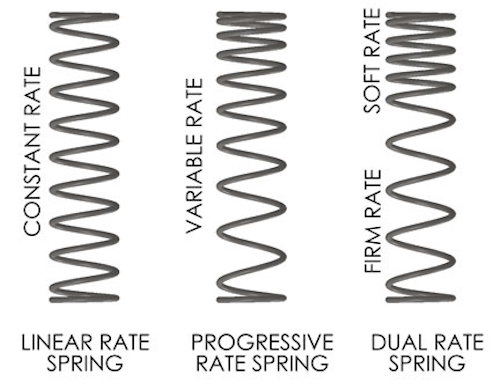
The spring body basically is a spiral, where the spring rate is controlled by the spacing of the coils. Given that we can control the machine, we can change the spacing on the fly resulting in being able to create differing spring rates using the same wire, in the same spring. If the spring spacing is consistent, the spring will have a constant rate of compression, if we slowly change the spring spacing we can generate a spring that changes spring rate when it compresses, and if we put two springs together we can have a dual rate.
Now let’s make some cool springs. The next one will breakdown the Gcode for making a fairly standard coil spring.