GRBL 3d wire bender, Part 4 : The Controller software

Although you can use the Serial Monitor in the Arduino IDE for testing the install of GRBL by opening the serial port at 115200 baud, I wanted something a little cooler to do that with, so here’s some software we can use to make it a lot easier to use. I have DSL still, as I live out in the middle of nowhere, so I’m not going to use something online like Fusion360, or ChilliPepper.

Manually doing stuff

The best lookup document I found is here: http://www.diymachining.com/downloads/GRBL_Settings_Pocket_Guide_Rev_B.pdf

The basic commands are found here: https://github.com/gnea/grbl/wiki/Grbl-v1.1-Commands

You can choose to manually type a bunch of stuff in, and run it… good luck with that.

Controller programs

I’ve so far used GrblPanel, and Universal Gcode Sender. Both have their flaws, but both sorta work.

GrblPanel

GrblPanel has one major flaw. It runs on Windows. I had to borrow a laptop from work to get a copy of windows. It spins the motors, and seems to be pretty good for just moving the motors manually.

You can get your very own copy here: https://github.com/gerritv/Grbl-Panel/releases

Universal Gcode Sender

This is the standard for GRBL that is not too bad. Fairly short learning curve, but you do have to install Java.

You can get your very own copy here: https://winder.github.io/ugs_website/

Raspberry PI CNC

There is one other option which seems like a better one in the long term.. add wifi to the bender using a Raspberry PI. Not sure I’m going to go down this road on this project,, maybe on my 3040 refit, but the link to do it is here: https://wiki.protoneer.co.nz/Raspberry_Pi_CNC_-_Quick_Start_Guide

GRBL 3d wire bender, Part 3 – Embedded software

Being a software programmer, I always want to reuse code, so GRBL makes it easy to do motor control programming, which I’ll cover later.

For our application, we need to rework the PWM pin on the arduino UNO we are using to output the stuff the servo needs to see. Standard GRBL uses this pin for the Z limit switch, so let’s liberate it.

Fortunately someone else has the same issue that we have had, when they were making a pen plotter. Their solution was to create MIGRBL.

Here’s the installation instructions onto our Arduino UNO

  1. download a copy of MIGRBL
  2. Add the library using Sketch -> Include Library -> Add .ZIP Libary
  3. run File->Examples>MIGRBL->grblUpload
  4. compile and upload the code to arduino.

Now we can test it.

GRBL 3d wire bender, Part 2: Generic wiring

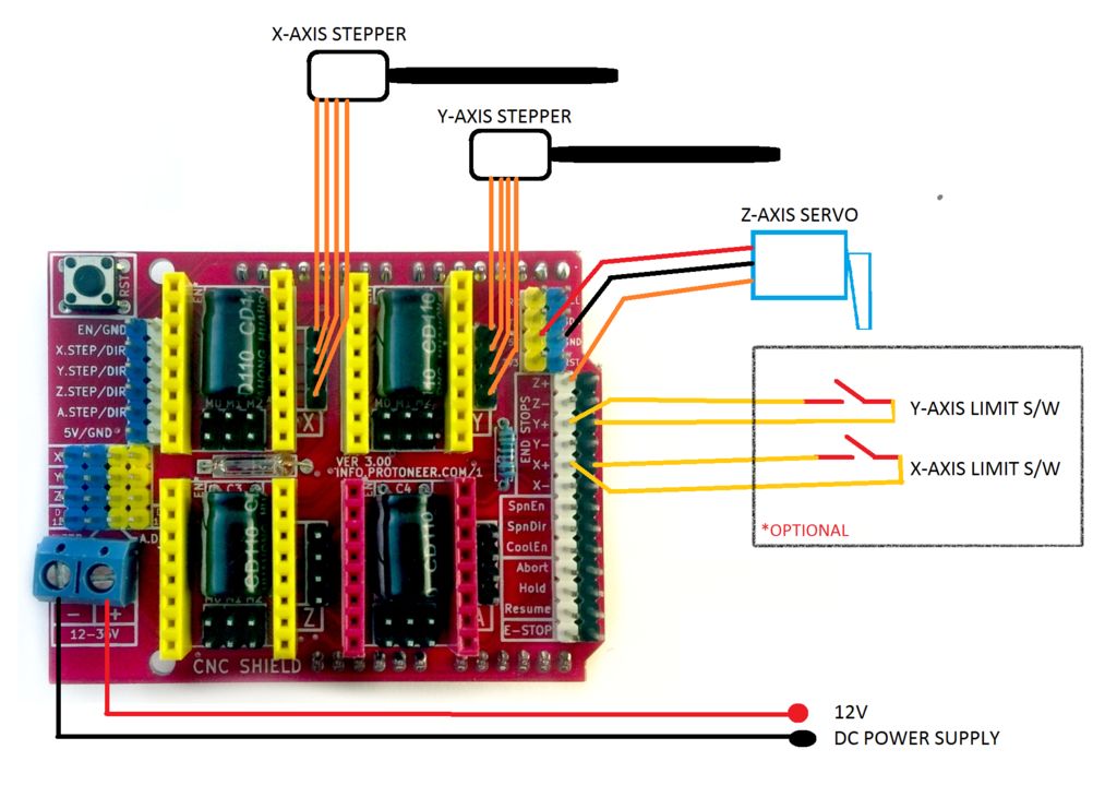
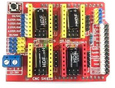
For the wire bender project I’m using a standard GRBL cnc shield on an Arduino Uno, Fairly standard stuff, that I had around.

GRBL CNC Shield

The servo motors are pretty simple hookup, with them plugging directly into the CNC, and adjusting the voltage similar to the instructions on http://www.zyltech.com/arduino-cnc-shield-instructions/.

1) Double check the power input polarity (“+” and “-“)

2) Be aware of the orientation of stepper drivers. Please note the potentiometer (pot) on A4988 and DRV8825 are at the opposite side​. If you are using the DRV8825 like I am, the pot goes next to the “CNC SHIELD” writing.

3) Adjust the max current, by adjusting the Vref

Max current = Vref x 2

Reference voltage is adjusted with a small screwdriver at the point indicated with the white arrow in the picture to the right. We suggest adjusting the reference voltage in small increments – no more than a quarter turn at a time. For a starting point, you may set the max current to 1A. If the motor over heats, reduce the Vref. If the motor does not move or miss steps, increase the Vref.

4) Plug in the X, Y and Z axis.

remember X is the rotation, Z is the feeder, and Y centrifugal motor. If you are rotating in the wrong direction, flip them around.

5) connect the limit switches, these are used to set the rotation of the X and Y axis. There is no Z limit switch

6) Connect the Servo Motor. Split the connector apart using a pocket knife or something similar, and put the yellow wire in the Z+, the red goes to the +5v, and the black to GND.

YAY… all of the wiring is done, onto the software to test things…

Updating GRBL, or any other Arduino Library in Windows

So GRBL that ships with Arduino is version 0.9. I needed version 1.1, Here’s a simple plan to update it.

Removing the old library

  1. Exit the Arduino IDE
  2. Goto C:\Program Files (x86)\Arduino\libraries on windows
  3. delete the folder for GRBL if you see it there..
  4. if it’s not there, it’s in your user folder at C:\Users\[your user name]\Documents\Arduino\libraries
  5. delete the folder for GRBL there.

Adding the new library

  1. Exit the Arduino IDE
  2. Goto C:\Users\[your user name]\Documents\Arduino\libraries
  3. copy the grbl folder into there.
  4. Restart your Arduino IDE

GRBL 3d wire bender, Part 1 Overview

I’ve been working on a 3d wire bender to make some springs, as I need them to be right, the first time, and every time after that.

First thing I did is look at a bunch of tutorials. So far not a one is perfect, but it’s got enough stuff to make a go at it.

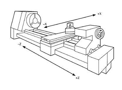
My idea is to set the device as a GCode unit, with the X being the rotation, the Y being the 2nd rotation axis, and the Z being the feed, similar to a Lathe.

Typical Lathe axis

in my case, it’s going to be a bit different as the machine has to look like this.

Image is courtesy of https://howtomechatronics.com/projects/arduino-3d-wire-bending-machine/

The Z axis rotates the bender unit around the wire, and the bender unit puts a crimp in it, which is running on the X axis. This leaves the feeder unit, which is basically a MIG wire welder feeder, but tied to a stepper motor so it can be moved out a specific distance as the Y axis.

The only odd thing is the pin at the end has to be able to push on both sides of the wire, so it has to be able to be raised and lowered on ether side of the existing bend. I’m going to use a servo to do this.

Suspension is important

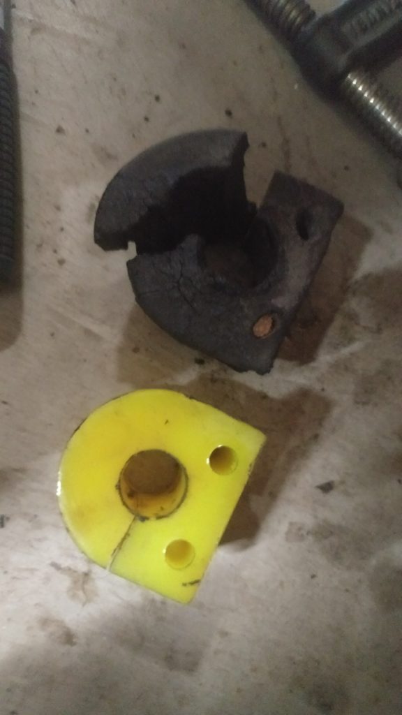
So the rubber in the discovery is 23 years old (happy birthday?) and it’s time to replace most of it. The rubber is old and cracked, sometimes even in half.

I’ve gone out and gotten new urethane bushings, which should help quite a bit. They of course are yellow to match the truck. Installing them turned out to be quite the annoyance, until I found out the trick.

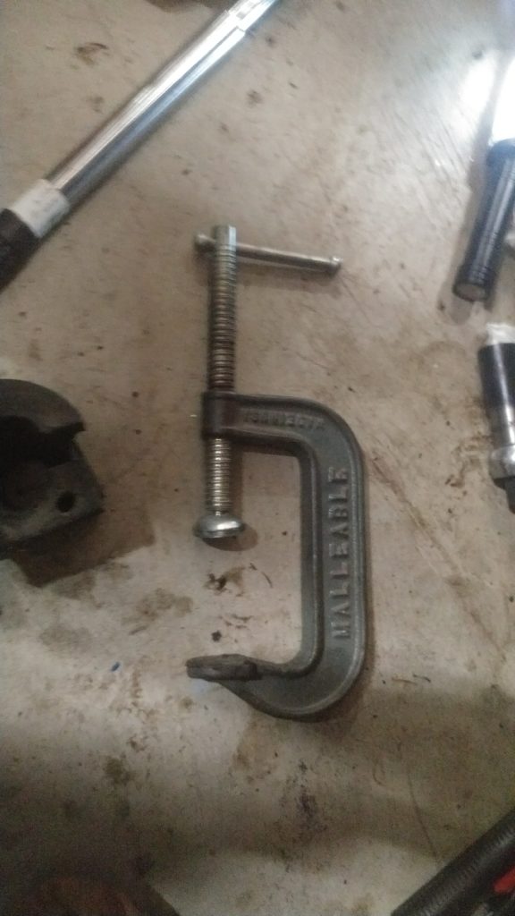
One big giant c clamp. The trick is to take the bushing, add lots of lube (in the form of synthetic axle grease and then stick the first bolt in, barely tight, but enough to grab over the retainer, and then use the c-clamp to the the side of the bushing to crush into the spot. I used the c-clamp on the side where the bushing is split, and then tightened the clamp down until the retainer touched the metal. Then I could tighten the other side.

add in the pile of tools, and the installation becomes easy.

Discovery Throttle Body Heat

So normally this is a system that gets thrown away very quickly, but seeing as I’m trying to build a truck that will be ok in cold, I’ll fix it. Underneath the throttle body / intake manifold, is a small plate.

Gems all the way!

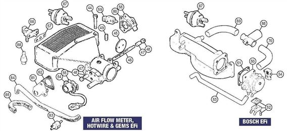
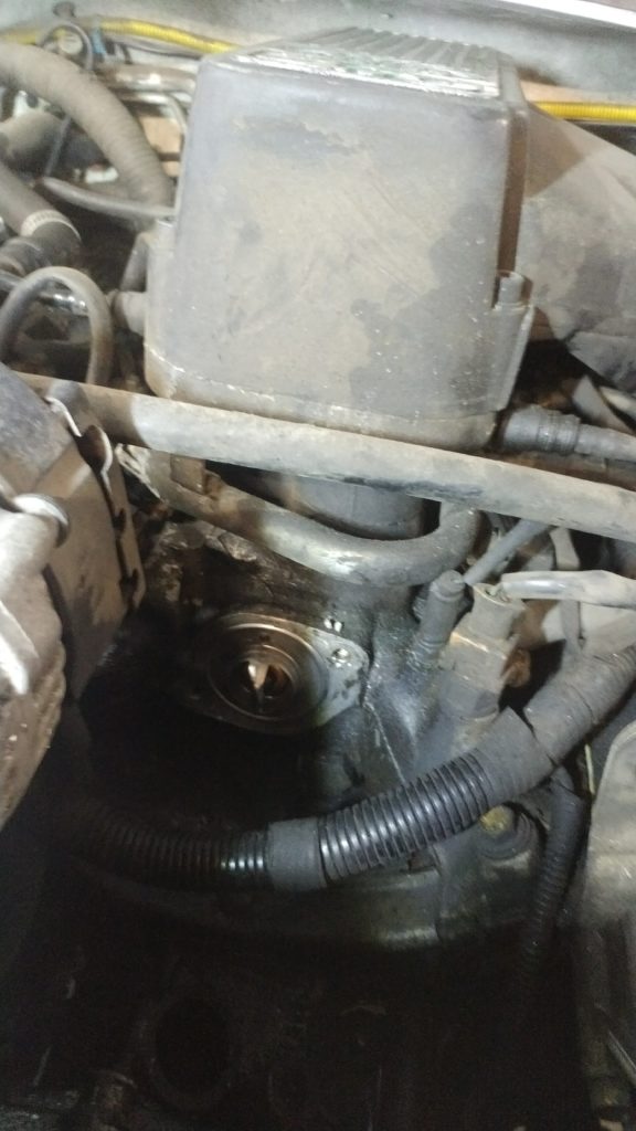
It’s labeled #48 on the diagram for the “air flow meter, hotwire and gems EFI” setup. Below is a picture of it in the truck. Really hard to see.

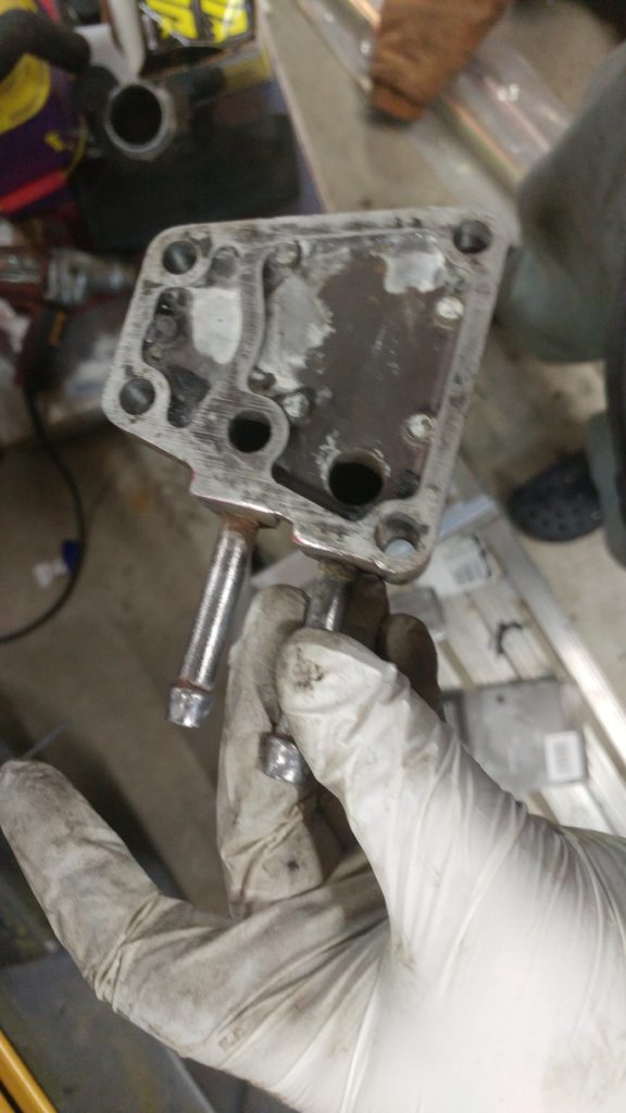
This plate acts as a heat exchanger to warm up the incoming air to prevent ice forming on the throttle body butterfly. Mine was trashed and rusty, and the gasket had dissolved leaving a lovely goop on the manifold.

Yummy! gasket left overs

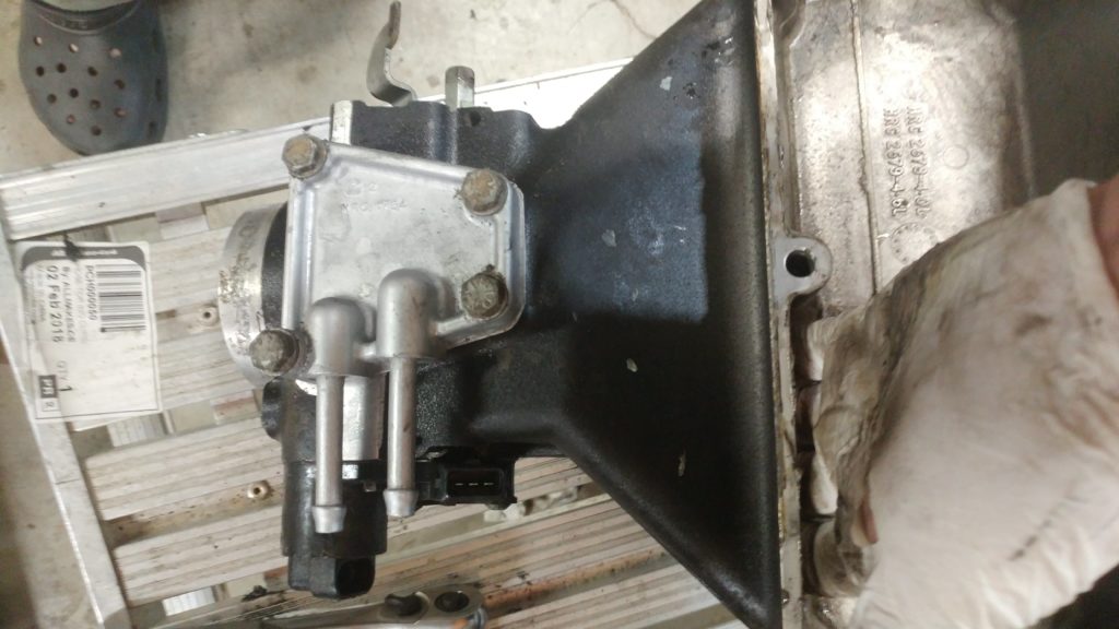
This was a fairly simple design and below is an example of how it’s supposed to look.

Here’s the part, cleaned up inside, without the gasket.

My gasket is trashed. Let’s make a new one using an old camper tail light.. The aluminum is about the same thickness as the gasket, and it will not galvanically corrode, unlike steel, and it’s not water soluble, like the original paper one.

Let’s make gaskets!

add some tin snips, a hole punch and some time, and we are ready to reinstall.

All better!

Discovery 1 Thermometers

I was working on replacing the hoses and thermometers on my disco, and I could not find any data on the differences over time for the thermometers. So I’ve put together some information.

The left thermometer is the stock one that was installed in 1996 in my truck. the right is the replacement part (etc4765). The changes are that It looks like the actual heater coil got bigger, and got fins on it. so it can soak up heat faster. The closer spring diameter is thicker, wound the other way, and has less turns. There is a bypass to equalize the pressure between both sides of the thermometer, and the stamping to retain the thermometer changed a bit. The diameter is the same, and I’ve put a standard socket to show size.

The gasket is fairly normal, so I’ll skip over that.

The filler neck I had developed some weeping holes, so I re-welded it, machined it and then gave it a good shot of paint. There is a bung here that could be used to add an external temperature sensor such as a ACDelco 213-77, or 15326386. The casting lines still showed, and that spot for the temperature sensor was not flat, so in a flury of dramatic OCD-ness, I fixed them.

The actual install is fairly straight forward, and it’s located underneath the intake runner, towards the front. right of the alternator from the front of the truck. The spigot curves up and to the left.

Radiator re-weld

So the fill cap on the Discovery’s really need a special wrench, which is ok because normally you don’t have to empty it that often. My truck never had a flush, since I bought it, and it had questionable service from some of the owners, it was about time. I used an adjustable wrench, the plastic radiator cap basically disintegrates. This was not a great idea.

Being that it’s 22 years old, it splits in the most annoying method possible, laterally. So I message it out with a screwdriver, a hammer and a chisel, straight into the radiator, not too bad, in that I can drain the radiator to get that out.

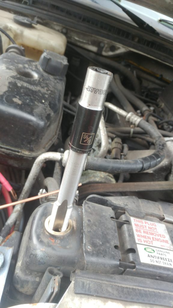
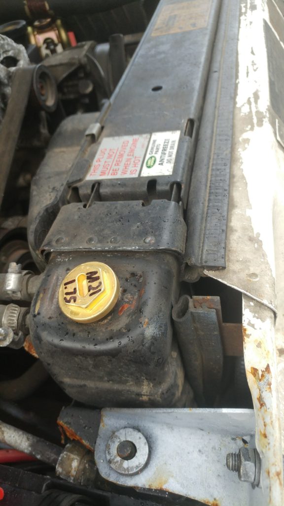
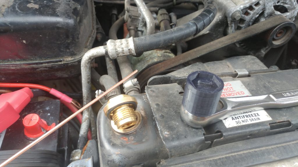
Atlantic British sells a brass replacement part (ERR4686B, $3.95) so after filling back in the brass with some filler rod, filing the neck down flat, and retapping the hole using a 21 x1.75mm tap and a 12 point 9/16 socket, the replacement fits in.

I did 3d print the special socket to screw the cap in this time, and installed the plug. The print is available on thingverse

In this whole process, the bottom hose broke, which is an odd design, which looks like the picture below, which was liberated from some auto parts seller who intern liberated it from the manufacturer.

I should redo it out of regular hose, but it’s only 22 bucks. It would be nice to add some features, like a coolant heater, and a drain plug. It could be made of a 45 degree copper fitting with two adapters soldered on, which would allow for a drain plug. Things left:

Things Completed:

  • New Transmission
  • New suspension, shocks, shock towers, etc
  • New Battery off a Ford F350 diesel

Things Left:

  • Steering leaks, Steering dampener, Sway bar links and hydraulic updates
  • Radios inside and out (2 din upgrade, external antenna, ham and CB radios
  • GPS, cameras, etc.
  • Other random stuff as it decides 22 years is enough.